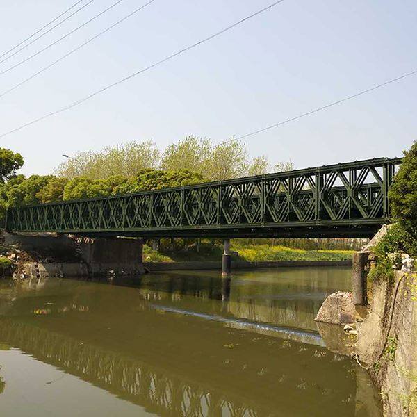
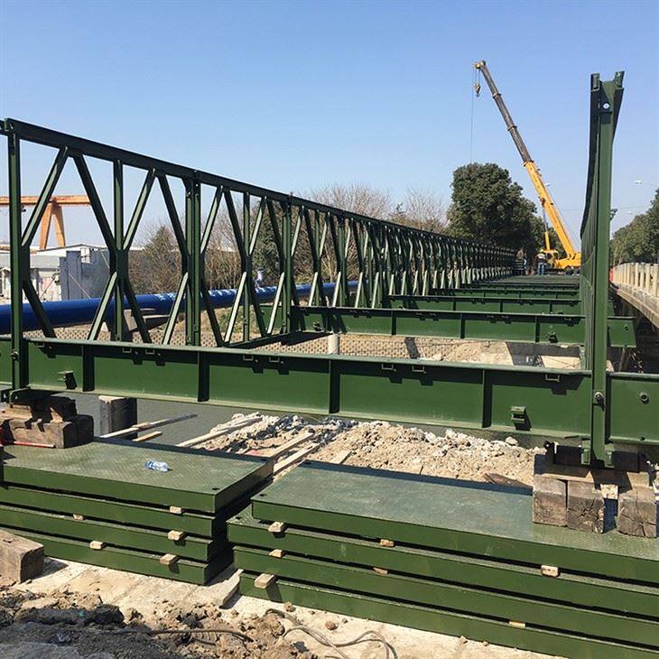
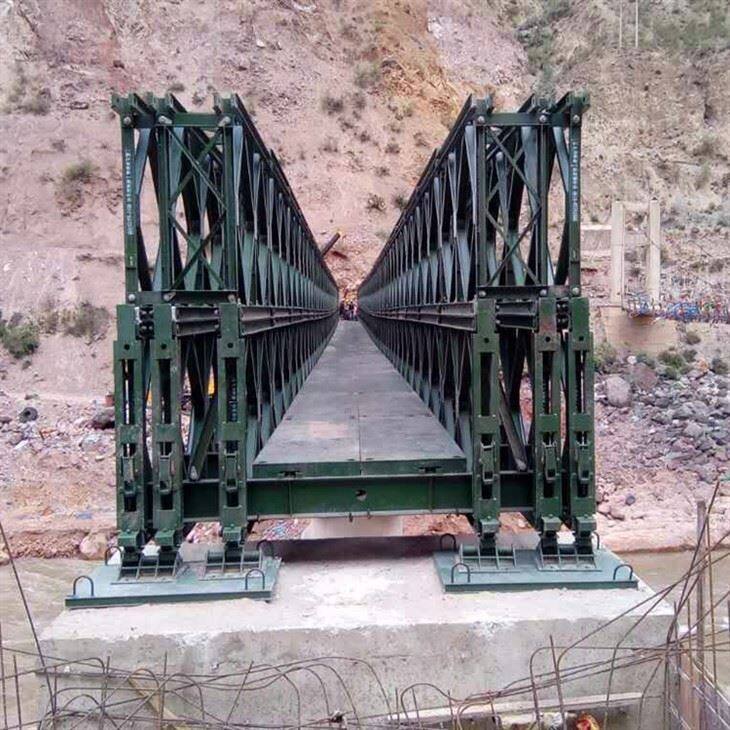
Product Structure
The core component of the Type 321 Bailey bridge is the standardized truss unit (Bailey panel). The standard dimensions of a single Bailey panel are 3 meters long, 1.5 meters wide, and 176 millimeters high, weighing approximately 270 kilograms. The truss consists of upper and lower chords (10-channel steel welded back to back), vertical members (8-beam steel), and diagonal members. The ends are equipped with male and female connectors and connecting pin holes for easy rapid assembly. By connecting multiple Bailey panels, bridges of different spans can be flexibly constructed. The applicable span range for a single span is 9 meters to 63 meters (simply supported beam), with a maximum span of 69 meters or 76.2 meters. Support frames are needed to reinforce the joints of multiple rows of trusses to enhance stability. Constructed from 16Mn high-strength steel, the components are highly interchangeable and connected by pins to ensure structural safety.
Product Categories
DSR


DDR


TS


TSR


TDR


8SR


| Component Quantity Table for Type 321 Reinforced Steel Bridge (U-shaped Steel Plate Bridge) | |||||||||||||||||||||||||||||||||||||||||||||||||||
| Combination form | Single-row single-layer reinforced type | Double-row single-layer reinforced type | Three-row single-layer reinforced type | Double-row double-layer reinforced type | Three-row double-layer reinforced type | ||||||||||||||||||||||||||||||||||||||||||||||
| Span (M) | 18 | 21 | 24 | 27 | 30 | 33 | 18 | 21 | 24 | 27 | 30 | 33 | 36 | 39 | 42 | 45 | 33 | 36 | 39 | 42 | 45 | 48 | 51 | 42 | 45 | 48 | 51 | 54 | 57 | 60 | 45 | 48 | 51 | 54 | 57 | 60 | 63 | 66 | 69 | ||||||||||||
| Number of Sections | 6 | 7 | 8 | 9 | 10 | 11 | 6 | 7 | 8 | 9 | 10 | 11 | 12 | 13 | 14 | 15 | 11 | 12 | 13 | 14 | 15 | 16 | 17 | 14 | 15 | 16 | 17 | 18 | 19 | 20 | 15 | 16 | 17 | 18 | 19 | 20 | 21 | 22 | 23 | ||||||||||||
| Truss | 12 | 14 | 16 | 18 | 20 | 22 | 24 | 28 | 32 | 36 | 40 | 44 | 48 | 52 | 56 | 60 | 66 | 72 | 78 | 84 | 90 | 96 | 102 | 112 | 120 | 128 | 136 | 144 | 152 | 160 | 180 | 192 | 204 | 216 | 228 | 240 | 252 | 264 | 275 | ||||||||||||
| Strengthening Rod | 16 | 20 | 24 | 28 | 32 | 36 | 32 | 40 | 48 | 56 | 64 | 72 | 80 | 88 | 96 | 104 | 108 | 120 | 132 | 144 | 156 | 168 | 180 | 96 | 104 | 112 | 120 | 128 | 136 | 44 | 156 | 168 | 180 | 192 | 204 | 216 | 228 | 240 | 252 | ||||||||||||
| Pin | 44 | 52 | 60 | 68 | 76 | 84 | 88 | 104 | 120 | 136 | 152 | 168 | 184 | 200 | 216 | 232 | 252 | 276 | 309 | 324 | 348 | 372 | 396 | 328 | 352 | 376 | 400 | 424 | 448 | 472 | 528 | 564 | 600 | 636 | 672 | 708 | |744 | 780 | 816 | ||||||||||||
| Crossbeam Fixture | 13 | 15 | 17 | 19 | 21 | 23 | 13 | 15 | 17 | 19 | 21 | 23 | 25 | 27 | 29 | 31 | 23 | 25 | 27 | 29 | 31 | 33 | 35 | 29 | 31 | 33 | 35 | 37 | 39 | 41 | 31 | 33 | 35 | 37 | 39 | 41 | 43 | 45 | 47 | ||||||||||||
| Crossbeam Fixture | 24 | 28 | 32 | 36 | 40 | 44 | 48 | 56 | 64 | 72 | 80 | 88 | 96 | 104 | 112 | 120 | 132 | 144 | 156 | 168 | 180 | 192 | 204 | 112 | 120 | 128 | 136 | 144 | 152 | 160 | 180 | 192 | 204 | 216 | 228 | 240 | 2252 | 264 | 276 | ||||||||||||
| Standard Bridge Deck | 24 | 28 | 32 | 36 | 40 | 44 | 48 | 56 | 64 | 72 | 80 | 88 | 96 | 104 | 112 | 120 | 132 | 144 | 156 | 168 | 180 | 192 | 204 | 112 | 120 | 128 | 136 | 144 | 152 | 160 | 180 | 192 | 204 | 216 | 228 | 240 | 252 | 264 | 276 | ||||||||||||
| Intermediate Bridge Deck | 6 | 7 | 8 | 9 | 10 | 11 | 6 | 8 | 9 | 10 | 11 | 12 | 13 | 14 | 15 | 11 | 12 | 13 | 14 | 15 | 16 | 17 | 14 | 15 | 16 | 17 | 18 | 19 | 20 | 15 | 16 | 17 | 18 | 19 | 20 | 21 | 22 | 23 | |||||||||||||
| Cutting Edge | 12 | 14 | 16 | 18 | 20 | 22 | 12 | 14 | 16 | 18 | 20 | 22 | 24 | 26 | 28 | 30 | 22 | 24 | 26 | 28 | 30 | 32 | 34 | 28 | 30 | 32 | 34 | 36 | 38 | 40 | 30 | 32 | 34 | 36 | 38 | 40 | 42 | 44 | 46 | ||||||||||||
| Positive End Column | 2 | 2. | 2 | 2 | 2 | 2 | 4 | 4 | 4 | 4 | 4 | 4 | 4 | 4 | 4 | 4 | 6 | 6 | 6 | 6 | 6 | 6 | 6 | 4 | 4 | 4 | 4 | 4 | 4 | 4 | 6 | 6 | 6 | 6 | 6 | 6 | 6 | 6 | 6 | ||||||||||||
| Negative End Column | 2 | 2 | 2 | 2 | 2 | 2 | 4 | 4 | 4 | 4 | 4 | 4 | 4 | 4 | 4 | 4 | 6 | 6 | 6 | 6 | 6 | 6 | 6 | 4 | 4 | 4 | 4 | 4 | 4 | 4 | 6 | 6 | 6 | 6 | 6 | 6 | 6 | 6 | 6 | ||||||||||||
| Diagonal Bracing Bolt | 14 | 16 | 18 | 20 | 22 | 24 | 14 | 16 | 18 | 20 | 22 | 24 | 26 | 28 | 30 | 32 | 24 | 26 | 28 | 30 | 32 | 34 | 36 | 30 | 32 | 34 | 36 | 38 | 40 | 42 | 32 | 34 | 36 | 38 | 40 | 42 | 44 | 46 | 48 | ||||||||||||
| Support Frame | - | - | - | - | - | - | 12 | 14 | 16 | 18 | 20 | 22 | 24 | 26 | 28 | 30 | 22 | 24 | 26 | 28 | 30 | 32 | 34 | 58 | 62 | 66 | 70 | 74 | 78 | 82 | 62 | 66 | 70 | 74 | 78 | 82 | 86 | 90 | 94 | ||||||||||||
| Connecting Plate | - | - | - | - | - | - | - | - | - | - | - | - | - | - | - | - | 24 | 26 | 28 | 30 | 32 | 34 | 36 | - | - | - | - | - | - | - | 64 | 68 | 72 | 76 | 80 | 84 | 88 | 92 | 96 | ||||||||||||
| Wind-Resistant Tie Rod | 12 | 14 | 16 | 18 | 20 | 22 | 12 | 14 | 16 | 18 | 20 | 22 | 24 | 26 | 28 | 30 | 22 | 24 | 26 | 28 | 30 | 32 | 34 | 28 | 30 | 32 | 34 | 36 | 38 | 40 | 30 | 32 | 34 | 36 | 38 | 40 | 42 | 44 | 46 | ||||||||||||
| Bridge Abutment | 4 | 4 | 4 | 4 | 4 | 4 | 8 | 8 | 8 | 8 | 8 | 8 | 8 | 8 | 8 | 8 | 8 | 8 | 8 | 8 | 8 | 8 | 8 | 8 | 8 | 8 | 8 | 8 | 8 | 8 | 8 | 8 | 8 | 8 | 8 | 8 | 8 | 8 | 8 | ||||||||||||
| Seat Plate | 4 | 4 | 4 | 4 | 4 | 4 | 4 | 4 | 4 | 4 | 4 | 4 | 4 | 4 | 4 | 4 | 4 | 4 | 4 | 4 | 4 | 4 | 4 | 4 | 4 | 4 | 4 | 4 | 4 | 4 | 4 | 4 | 4 | 4 | 4 | 4 | 4 | 4 | 4 | ||||||||||||
| Chord Bolt | 32 | 40 | 48 | 56 | 64 | 72 | 64 | 80 | 96 | 112 | 128 | 144 | 160 | 176 | 192 | 208 | 216 | 240 | 264 | 288 | 312 | 336 | 360 | 292 | 308 | 324 | 340 | 356 | 372 | 388 | 312 | 336 | 360 | 384 | 408 | 432 | 456 | 480 | 504 | ||||||||||||
| Diagonal Bracing Bolt | 28 | 32 | 36 | 40 | 44 | 48 | 28 | 32 | 36 | 40 | 44 | 48 | 52 | 56 | 60 | 64 | 48 | 52 | 56 | 60 | 64 | 68 | 72 | 60 | 64 | 68 | 72 | 76 | 80 | 84 | 64 | 68 | 72 | 76 | 80 | 84 | 88 | 92 | 96 | ||||||||||||
| Bridge Frame Bolt | - | - | 48 | 56 | 64 | 72 | 80 | 88 | 96 | 104 | 112 | 120 | 88 | 96 | 104 | 112 | 120 | 128 | 136 | 232 | 248 | 264 | 280 | 296 | 312 | 328 | 248 | 264 | 280 | 296 | 312 | 328 | 344 | 360 | 376 | ||||||||||||||||
| Type 1 Bolt | 63 | 72 | 81 | 90 | 99 | 108 | 63 | 72 | 81 | 90 | 99 | 108 | 117 | 126 | 135 | 144 | 108 | 117 | 126 | 135 | 144 | 153 | 162 | 135 | 144 | 153 | 162 | 171 | 180 | 189 | 144 | 153 | 162 | 171 | 180 | 189 | 198 | 207 | 216 | ||||||||||||
| M20 Bolt | 60 | 70 | 80 | 90 | 100 | 110 | 60 | 70 | 80 | 90 | 100 | 110 | 120 | 130 | 140 | 150 | 110 | 120 | 130 | 140 | 150 | 160 | 170 | 140 | 150 | 160 | 170 | 180 | 190 | 200 | 150 | 160 | 170 | 180 | 190 | 200 | 210 | 220 | 230 | ||||||||||||
|
Note: 1. No reinforcing bars are installed on the first two sections of the bridge. 2. The number of components listed in the table does not include the amount used for the access roads to the steel bridge. |
|||||||||||||||||||||||||||||||||||||||||||||||||||
Product Advantages
- Rapid Assembly: Modular components allow for quick assembly and disassembly, suitable for emergency rescue and temporary projects.
- High Strength and Lightweight: Steel structures are relatively high-strength and lightweight, resulting in low transportation costs; they can be transported in bulk using ordinary vehicles.
- High Flexibility: Span, lanes, and loads can be adjusted to different terrains.
- Easy Interchangeability: Standardized, universal components facilitate maintenance and replacement, reducing costs.
- Wide Application: Compatible with various foundation types and adaptable to complex geological conditions.
Application Scenarios
- Emergency Support:Rapidly clearing temporary access routes for flood control, earthquake relief, and military operations.
- Infrastructure Construction:Temporary bridges for bridge construction, construction platforms across rivers or roads, and precast beam storage supports.
- Municipal and rural transportation: temporary bridges across streams in rural areas, temporary access roads for municipal pipeline construction, and pedestrian or vehicular bridges in scenic areas.
- Other: access roads for mining operations, access roads for oil fields, and temporary access roads for events/exhibitions, etc.
If you need more information about the 321 Bailey bridge or want to get a quote, please feel free to contact me. I will provide you with professional service!


